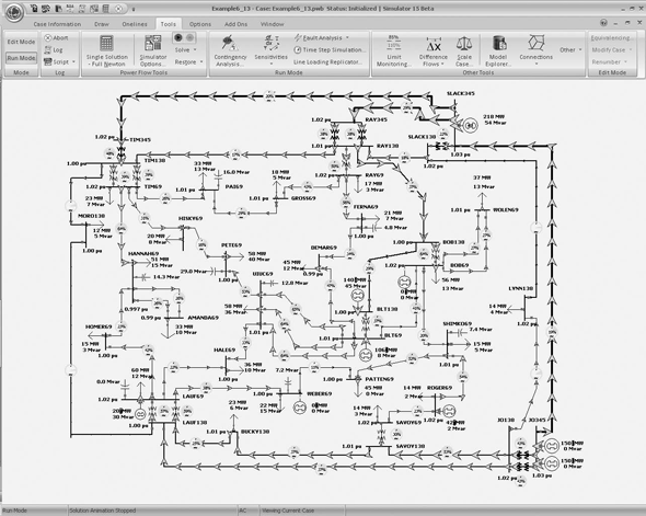

- #NUMBER OF BUSES LIMIT FOR POWER WORLD SIMULATOR 19 GENERATOR#
- #NUMBER OF BUSES LIMIT FOR POWER WORLD SIMULATOR 19 SERIES#
The lines with high R/X ratio is considered to incorporate the series device TCSC and combined series-shunt device UPFC because lines which have high R/X ratio are tend to diverge as discussed by many researchers. Incase of divergence, the line having next highest R/X ratio is considered for locating FACTS devices. The line having highest R/X ratio is given first priority. 4Q3 Based on the R/X ratio, FACTS devices are inserted. of sets considered for this study is to observe the point of divergence and ill conditionality. of iterations and also there is increase in maximum power mismatch.

4Q2 The effect of varying resistance from 1 to 4 times the original case on the load flow solution results in increased no. The transmission line connected between buses 12 and 13 has an R/X ratio of which is beyond the prescribed range. This observation is same even with the incorporation of FACTS devices. Further increase in the line resistance has crossed the prescribed range and when the line resistance is increased beyond 4 times, the test system has diverged. The observations made in this study, The R/X ratio is with in the prescribed range when the line resistance is increased by 2.5 times the base case. The resistance part of every line for IEEE-14 bus test system is increased by 4 times in steps of 0.5 times to create ill conditionality and to check for convergence with and without the incorporation of FACTS devices.
#NUMBER OF BUSES LIMIT FOR POWER WORLD SIMULATOR 19 GENERATOR#
1 APPENDIX-I : BUS DATA FOR IEEE-14 BUS SYSTEM Bus Bus Voltage Angle Load Generator Injected No Code Magnitude Degrees MW MVAR MW MVAR Qmin Qmax MVARĢ APPENDIX-II : LINE DATA FOR IEEE-14 BUS SYSTEM Sendind end Bus Receiving end Bus Resistance Reactance Half Susceptance Tranformer tapģ APPENDIX-III : BUS DATA FOR 13-BUS ILL-CONDITIONED SYSTEM Bus Bus Voltage Angle Load Generator Injected No Code Magnitude Degrees MW MVAR MW MVAR Qmin Qmax MVARĤ APPENDIX-IV : LINE DATA FOR 13-BUS ILL-CONDITIONED SYSTEM Sendind end Bus Receiving end Bus Resistance Reactance Half Susceptance Tranformer tapĥ APPENDIX-V : BUS DATA FOR 11-BUS ILL-CONDITIONED SYSTEM Bus Bus Voltage Angle Load Generator Injected No Code Magnitude Degrees MW MVAR MW MVAR Qmin Qmax MVARĦ APPENDIX-VI : LINE DATA FOR 11-BUS ILL-CONDITIONED SYSTEM Sendind end Bus Receiving end Bus Resistance Reactance Half Susceptance Tranformer tapħ APPENDIX-VII: SINGLE LINE DIAGRAM OF IEEE-14 BUS SYSTEM Figure: IEEE 14 Bus test systemĨ APPENDIX-VIII SINGLE LINE DIAGRAM OF 13-BUS ILL-CONDITIONED SYSTEM G G G G G G Figure: 13 Bus ill-conditioned power systemĩ APPENDIX-IX SINGLE LINE DIAGRAM OF 11-BUS ILL-CONDITIONED SYSTEM Figure: 11 Bus ill-conditioned power systemġ0 APPENDIX-X: CLARIFICATIONS TO QUERIES 4Q1: The prescribed range of R/X ratio for a transmission line is 0 to 1.


 0 kommentar(er)
